产品介绍
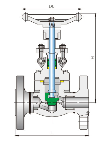
产品结构特点 Construction features
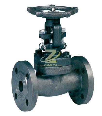
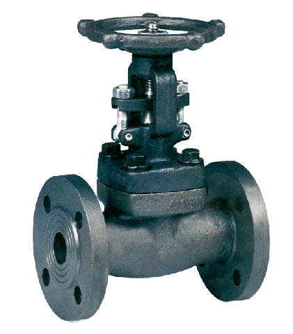
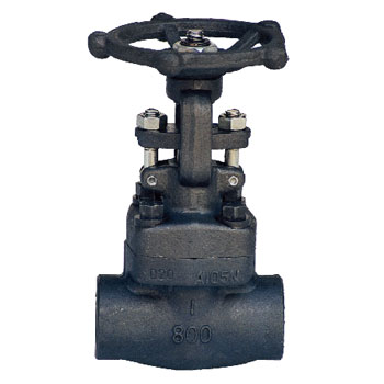
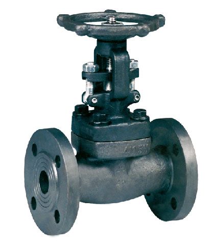
内螺纹与承插焊截止阀的闭合原理是,依靠阀杠压力,使阀瓣密封面与阀座密封面紧密贴合,阻止介质流通。截止阀只许介质单向流动,安装时有 方向性。截止阀的结构 长度大于闸阀,同时流体阻力大,长期运行时,密封可靠性不强。
The closed principle of the internal screw and socket welding stop valve is to rely on the stem pressure to close the sealing cover of the disc and the sealing cover of the seat to prevent the circulation of the medium. The globe valve only allows the medium to flow in one direction, and the installation has directivity. The globe valve has a structure length greater than gate valve, while fluid resistance is large, and the sealing reliability is not strong in the long run.
技术规范 Technical specification
| 设计依据 Design reference | GB系列 GB series |
| 设计标准 Design standard | GB/T12235 |
| 结构长度 Face to face | GB/T12221 |
| 连接法兰 End flange | GB/T9113 HG20592 |
| 试验和检验 Test & inspection | GB/T 26480 |
试验压力 Test prssure
|
压力等级 Pressure grade |
试验压力 Test pressure | |||
|
公称压力 PN Nominal pressure |
壳体试验 Sheil test |
正密封试验 Sealing test |
反密封试验 Sealing test |
气密封试验 Air seal test |
| 1.6 | 2.4 | 1.76 | 1.76 | 0.6 |
| 2.5 | 3.75 | 2.75 | 2.75 | 0.6 |
| 4.0 | 6.0 | 4.4 | 4.4 | 0.6 |
| 6.3 | 9.45 | 6.93 | 6.93 | 0.6 |
| 10.0 | 15.0 | 11.0 | 11.0 | 0.6 |
| 16.0 | 24.0 | 17.6 | 17.6 | 0.6 |
| 26.0 | 39.0 | 28.5 | 28.5 | 0.6 |
截止阀结构长度和外接尺寸 Main connection dimensions
| PN:1.6~4.0 | PN:6.4~10.0 | |||||
|
公称通径 DN |
L (mm) |
H (mm) |
D0 (mm) |
L (mm) |
H (mm) |
D0 (mm) |
| 15 | 130 | 180 | 100 | 170 | 180 | 100 |
| 20 | 150 | 175 | 100 | 190 | 190 | 100 |
| 25 | 160 | 210 | 125 | 210 | 230 | 125 |
| 32 | 180 | 240 | 160 | 230 | 240 | 160 |
| 40 | 200 | 270 | 160 | 260 | 270 | 160 |
| 50 | 230 | 300 | 180 | 300 | 285 | 180 |
| PN:26.0 | |||
|
公称通径 DN |
L (mm) |
H (mm) |
D0 (mm) |
| 15 | 216 | 195 | 125 |
| 20 | 229 | 200 | 125 |
| 25 | 254 | 230 | 160 |
| 32 | 279 | 235 | 160 |
| 40 | 305 | 260 | 180 |
| 50 | 371 | 340 | 200 |


