产品介绍
产品结构特点 Construction features
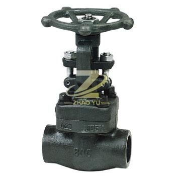
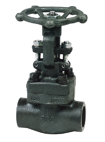
内螺纹与承插焊锻钢闸阀流体阻力小,启、闭所需力矩较小,可以使用在介质向两方向流动的环网管路上,也就说介质流向不受限制。全开时,密封面受工作介质的冲 蚀比截止阀小。形体结构比较简单,制造工艺性较好,结构长度比较短。
The internal thread and the welded steel gate valve are small in the fluid resistance, and the torque is small, and can be used in the two directions of the loop network tube, which also means that the flow of the medium is not restricted. When open, the sealing cover is less than the closing valve of the working medium. The form structure is relatively simple, the manufacturing process is better, the structure length is shorter.
技术规范 Technical specification
| 设计依据 Design reference | GB系列 GB series |
| 设计标准 Design standard | GB/T12234 |
| 结构长度 Face to face | GB/T12221 |
| 连接法兰 End flange | GB/T12224 |
| 试验和检验 Test & inspection | GB/T26480 |
试验压力 Test prssure
|
压力等级 Pressure grade |
试验压力 Test pressure | |||
|
公称压力 PN Nominal pressure |
壳体试验 Sheil test |
正密封试验 Sealing test |
反密封试验 Sealing test |
气密封试验 Air seal test |
| 1.6 | 2.4 | 1.76 | 1.76 | 0.6 |
| 2.5 | 3.75 | 2.75 | 2.75 | 0.6 |
| 4.0 | 6.0 | 4.4 | 4.4 | 0.6 |
| 6.3 | 9.45 | 6.93 | 6.93 | 0.6 |
| 10.0 | 15.0 | 11.0 | 11.0 | 0.6 |
| 16.0 | 24.0 | 17.6 | 17.6 | 0.6 |
| 26.0 | 39.0 | 28.5 | 28.5 | 0.6 |
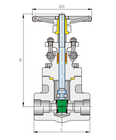
闸阀结构长度和外接尺寸 Main connection dimensions
| PN:1.6~6.4 | PN:10.0~26.0 | |||||
|
公称通径 DN |
L (mm) |
H (mm) |
D0 (mm) |
L (mm) |
H (mm) |
D0 (mm) |
| 15 | 79 | 180 | 100 | 111 | 195 | 125 |
| 20 | 92 | 185 | 100 | 111 | 195 | 125 |
| 25 | 111 | 215 | 125 | 120 | 220 | 160 |
| 32 | 120 | 225 | 160 | 120 | 245 | 160 |
| 40 | 120 | 245 | 160 | 140 | 280 | 180 |
| 50 | 140 | 285 | 180 | 178 | 305 | 200 |


