产品介绍
产品结构特点 Construction features
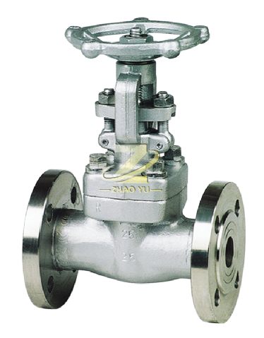
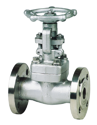
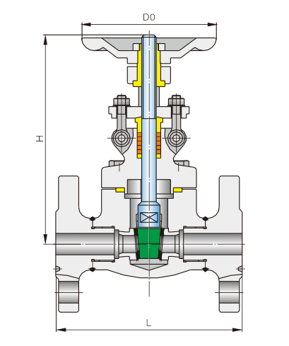
锻钢法兰端闸阀有三种阀盖设计形式。第一种是螺栓式阀盖,按这种设计的阀门,其阀体与阀盖用螺栓螺母连接,缠绕式垫片(316夹柔性石墨制造)。客户有特殊要求时也可采用金属环连接。
There are three types of bonnet design for forged flange end valves. The first type is bolted bonnet, which is designed to connect the valve body to the bonnet with bolt nuts and coil gasket (316 clip flexible graphite). Metal ring connections may also be used when customers have special requests.
产品特征 Spericfications
适用介质:水、气、油品、天然气和酸碱腐蚀性介质
适用温度:-196~425℃
驱动方式:手动、气动、电动等
公称压力:1.6~16.0MPa
公称通径:DN15~50mm
Applicable media: water, gas, oil, gas and acid and alkali corrosive medium
Applicable temperature: -196~425℃
Driver: manual, pneumatic, electric, etc
Nominal pressure: 1.6~16.0MPa
Nominal size: DN15~50mm
技术规范 Technical specification
| 设计依据 Design reference | GB系列 GB series |
| 设计标准 Design standard | GB/T12234 |
| 结构长度 Face to face | GB/T12221 |
| 连接法兰 End flange | GB/T9113 HG20592 |
| 试验和检验 Test & inspection | GB/T26480 |
试验压力 Test prssure
|
压力等级 Pressure grade |
试验压力 Test pressure | |||
|
公称压力 PN Nominal pressure |
壳体试验 Sheil test |
正密封试验 Sealing test |
反密封试验 Sealing test |
气密封试验 Air seal test |
| 1.6 | 2.4 | 1.76 | 1.76 | 0.6 |
| 2.5 | 3.75 | 2.75 | 2.75 | 0.6 |
| 4.0 | 6.0 | 4.4 | 4.4 | 0.6 |
| 6.3 | 9.45 | 6.93 | 6.93 | 0.6 |
| 10.0 | 15.0 | 11.0 | 11.0 | 0.6 |
| 16.0 | 24.0 | 17.6 | 17.6 | 0.6 |
| 26.0 | 39.0 | 28.5 | 28.5 | 0.6 |
闸阀结构长度和外接尺寸 Main connection dimensions
| PN:1.6~4.0 | PN:6.4~10.0 | |||||
|
公称通径 DN |
L (mm) |
H (mm) |
D0 (mm) |
L (mm) |
H (mm) |
D0 (mm) |
| 15 | 130 | 180 | 100 | 170 | 180 | 100 |
| 20 | 150 | 185 | 100 | 190 | 185 | 100 |
| 25 | 160 | 215 | 125 | 210 | 215 | 125 |
| 32 | 180 | 225 | 160 | 230 | 225 | 160 |
| 40 | 200 | 245 | 160 | 240 | 245 | 160 |
| 50 | 250 | 285 | 180 | 250 | 285 | 180 |
| PN:16.0 | PN:26.0 | |||||
|
公称通径 DN |
L (mm) |
H (mm) |
D0 (mm) |
L (mm) |
H (mm) |
D0 (mm) |
| 15 | 170 | 195 | 125 | 216 | 195 | 125 |
| 20 | 190 | 195 | 125 | 229 | 195 | 125 |
| 25 | 210 | 220 | 160 | 254 | 220 | 160 |
| 32 | 230 | 245 | 160 | 279 | 245 | 160 |
| 40 | 260 | 280 | 180 | 305 | 280 | 180 |
| 50 | 300 | 305 | 200 | 368 | 305 | 200 |


