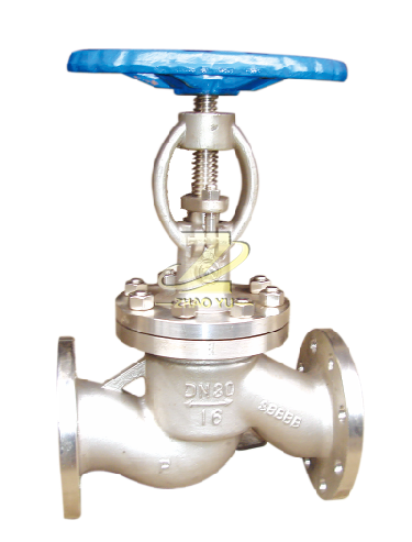
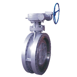
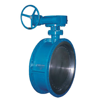
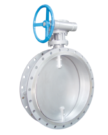
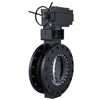
Product Introduction
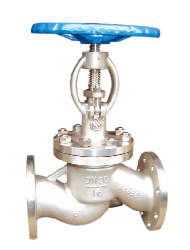
产品结构特点 Construction features
1)、本系列阀门主体采用铸锻结构,具有平行双密封副半强制双向密封,密封面到位运动和楔紧运动分步作用,实现零泄露。
2)、密封面之间摩擦系数小,起闭方便,而且,密封面的磨损有自动补偿功能。
3)、结构简单,紧凑,检修方便,使用寿命长。
4)、阀盖填料室设有真空密封机构,具有自胀压紧作用,并且,各连接面采用高强膨胀材料密封,使系统与大气隔离,具有良好的真空密封性能。
5)、本系列阀门连接形式可为法兰连接及焊接连接两种,驱动方式为手动、电动两种。尤其适用于火电厂汽机冷凝和真空负压系统,起到真空密封隔离作用。
1) the main body of this series of valves adopts the cast forging structure, which has the double seal of the parallel double seal, the sealing of the sealing surface of the valve is in place, and the movement of the sealing cover in place and the step of the wedging movement are used to realize zero leakage.
2) the friction coefficient between the sealing surface is small, and it is convenient to operate. Moreover, the wear of the sealing surface has automatic compensation function.
3) simple structure, compact, convenient maintenance, long service life.
4), the cover packing room equipped with vacuum sealing mechanism, have since the expansion pressure effect, and the junction surface using high-strength packing material, make the system from the atmosphere, has a good vacuum seal performance.
5) the valve connection form of this series can be two kinds of flange connection and welding connection, and the driving mode is manual and electric. Especially suitable for the condensing and vacuum negative pressure system of the power plant.
产品特征 Spericfications
适用介质:水、气、油品、天然气和酸碱腐蚀性介质
适用温度:-196~425℃
驱动方式:手动、气动、电动等
公称压力:1.0~10.0MPa
公称通径:DN50~500mm
Applicable media: water, gas, oil, gas and acid and alkali corrosive medium
Applicable temperature: -196~425℃
Driver: manual, pneumatic, electric, etc
Nominal pressure: 1.0 ~ 10.0MPa
Nominal size: DN50~500mm
技术规范 Technical specification
| 设计依据 Design reference | GB系列 GB series |
| 设计标准 Design standard | GB/T12235 |
| 结构长度 Face to face | GB/T12221 |
| 连接法兰 End flange | GB/T9113 HG20592 |
| 试验和检验 Test & inspection | GB/T 26480 |
试验压力 Test prssure
|
压力等级 Pressure grade |
试验压力 Test pressure | |||
|
公称压力 PN Nominal pressure |
壳体试验 Sheil test |
正密封试验 Sealing test |
反密封试验 Sealing test |
气密封试验 Air seal test |
| 1.0 | 1.5 | 1.1 | 1.1 | 0.6 |
| 1.6 | 2.4 | 1.76 | 1.76 | 0.6 |
| 2.5 | 3.75 | 2.75 | 2.75 | 0.6 |
| 4.0 | 6.0 | 4.4 | 4.4 | 0.6 |
| 6.3 | 9.45 | 6.93 | 6.93 | 0.6 |
| 10.0 | 15.0 | 11.0 | 11.0 | 0.6 |
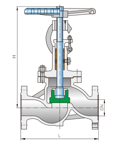
截止阀结构长度和外接尺寸 Main connection dimensions
| PN:1.6~4.0 | PN:6.3~10.0 | |||||
|
公称通径 DN |
L (mm) |
H (mm) |
D0 (mm) |
L (mm) |
H (mm) |
D0 (mm) |
| 50 | 230 | 280 | 220 | 300 | 360 | 240 |
| 65 | 290 | 350 | 240 | 340 | 400 | 280 |
| 80 | 310 | 360 | 280 | 380 | 480 | 320 |
| 100 | 350 | 410 | 320 | 430 | 530 | 350 |
| 125 | 400 | 450 | 350 | 500 | 600 | 400 |
| 150 | 480 | 480 | 400 | 550 | 680 | 450 |
| 200 | 600 | 600 | 450 | 650 | 750 | 550 |
| 250 | 650 | 720 | 550 |
|
|
|
| 300 | 750 | 950 | 650 |
|
|
|
| 350 | 850 | 1040 | 750 |
|
|
|
| 400 | 950 | 1150 | 800 |
|
|
|
| 450 | 1050 | 1250 | 850 |
|
|
|
| 500 | 1150 | 1380 | 950 |
|
|
|


